


5 dagen per week van 8:30 tot 17:30 uur

Range Hood Light Wiring Integration: Cable Length, Connector Position, and Strain Relief
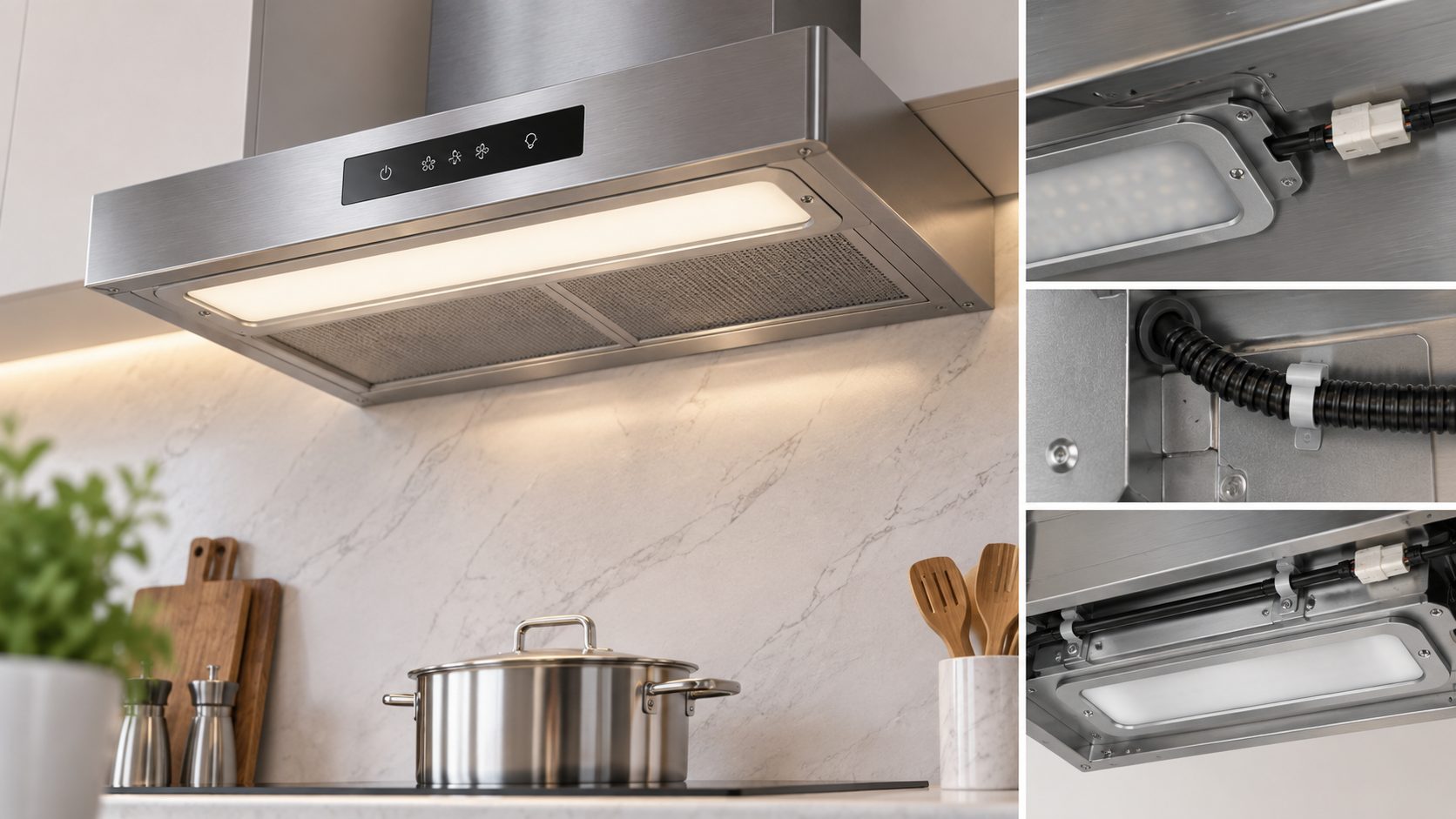
A commercial range hood light can meet the specified voltage, dimensions, and light output yet still create assembly problems if its cable is too short, exits from the wrong side, or places strain directly on the internal connection. For OEM production, wiring details need to be treated as part of the fixture interface rather than left for technicians to solve at the assembly station. The cable route often competes with folded sheet metal, ducts, brackets, insulation, and other electrical components inside the hood. A reliable specification therefore defines where the cable leaves the housing, how far it needs to reach, how it is restrained, and where the final electrical connection will sit.
How should cable length be calculated for the actual hood route?
The shortest distance between the light and the connection point is rarely the same as the installed cable path. Inside the hood, the cable may need to turn around brackets, follow a panel edge, or stay clear of another component.
Buyers reviewing commercial range hood lights should therefore measure the intended routing path rather than specifying a cable length from the fixture drawing alone.
Follow the production route, not a straight line
Start at the defined cable exit point and trace the route to the connector or terminal. Include each change in direction and any location where the cable is clipped or retained.
The finished cable length should include enough allowance for assembly and intended servicing, but not so much that large loops remain unsupported inside the hood.
Too little cable creates tension and makes connection difficult. Too much cable creates another problem: excess loops may occupy service space or move into areas not intended for wiring.
The approved length should therefore come from the real routing path.
Why must the cable exit position be controlled on the fixture drawing?
The cable outlet is part of the mechanical envelope of the light. A small change in outlet location can make a fixture difficult to install even when its housing dimensions remain unchanged.
A rear outlet may work well in one hood but interfere with a frame member in another. A side outlet can simplify routing or create a conflict with a folded edge.
The exit position should be dimensioned from fixed housing edges.
| Interface Detail | What Should Be Defined |
|---|---|
| Exit face | rear, side, or end |
| Exit position | distance from fixed edges |
| Cable length | finished length |
| Bend space | free area after cable exit |
| Retention point | first clip or support |
| Connector location | final connection position |
These items should be reviewed together because they affect the same routing path.
For non-standard layouts, the OEM customization process can support drawing confirmation before the production sample is released.
Check bend space immediately after the outlet
A fixture may fit the cutout but still force the cable into a tight bend if a bracket sits directly behind the outlet.
The first few centimeters of cable route deserve special attention because this is where strain is most likely to transfer into the fixture housing.
What should strain relief achieve in normal assembly and service?
Strain relief is not just a visible fitting at the cable entry. Its purpose is to prevent normal cable movement from being transferred directly into the internal electrical connection.
The correct construction can vary, so buyers should focus on the expected result.
During sample review, check whether the cable stays securely positioned where it enters the housing. Moderate assembly handling should not pull the cable deeper into the fixture or allow the entry point to shift.
Inspect the cable entry as a complete interface
Look for sufficient bend space, stable retention, and protection from unsuitable sharp edges. The cable should not twist the fixture or interfere with the mounting surface.
A useful sample check includes:
-
cable remains stable at the housing entry;
-
no sharp metal edge contacts the cable;
-
the route does not require an immediate tight bend;
-
cable movement does not transfer directly into the fixture;
-
mounting does not pinch or trap the cable;
-
the assembly remains repeatable across more than one sample.
The buyer does not need to invent a universal pull force unless the project specifies one. The inspection should represent real assembly and service handling.
Where should the connector sit for production and maintenance access?
A connector can be electrically correct and still be inconvenient if it is hidden behind a permanent panel or located where assembly workers cannot reach it without disturbing other components.
Connector placement should therefore be reviewed from two viewpoints: production assembly and later maintenance.
The final disconnect point needs enough space for the intended connector or terminal arrangement and enough cable allowance to make that connection without tension.
For hoods with several lights, consistent connector positions can simplify harness design and reduce assembly variation.
The broader commercial kitchen component catalog can help equipment designers coordinate lighting with surrounding hardware, but the connector location still needs to be controlled in the hood wiring layout.
Service access should be checked before the drawing is frozen
Remove and reinstall the sample fixture once using the intended maintenance method. If the technician can only reach the connector after removing unrelated panels or pulling other wiring out of position, the connection point may need to move.
A good OEM layout supports both the original assembly and realistic future service.
What should be verified on the first production-representative hood?
Cable routing cannot be approved reliably with the light sitting loose on a workbench. The sample needs to be installed in a real or production-equivalent hood.
Fit the fixture with the intended mounting hardware and route the cable exactly as a production operator would.
Then inspect the complete path:
-
outlet position matches the drawing;
-
cable reaches the connector without tension;
-
excess cable remains controlled;
-
strain relief stays seated;
-
the cable avoids unsuitable sharp edges;
-
retention points hold the route consistently;
-
the connector is reachable during assembly;
-
intended service access remains possible;
-
no bracket or duct forces a sharp bend;
-
routing can be repeated on another sample.
After installation, remove the light once and reinstall it. That simple step often reveals whether the cable allowance is realistic or whether the first assembly only worked because the operator had unusual access.
The approved routing should then be added to the released wiring or mechanical drawing.
Professional Technical Support from Foshan Simple Technology Co., Ltd.
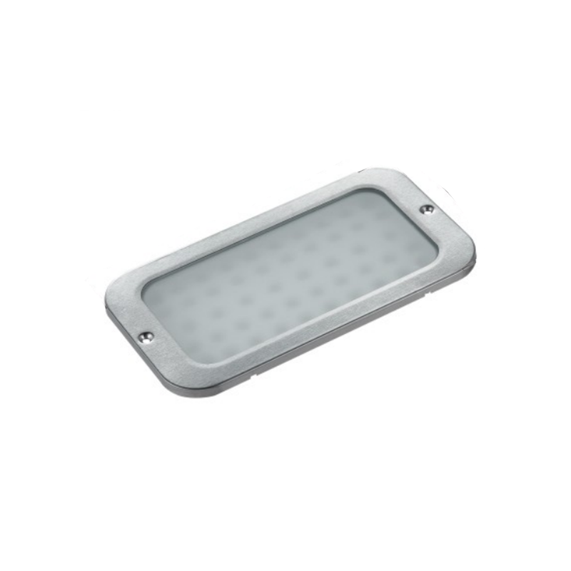
Foshan Eenvoudige Technologie Co., Ltd. supplies commercial kitchen components for OEM and distribution projects, including commercial range hood lights in several housing formats and sizes. One product reference is the SP-232BH Range Hood Anti Oil Fume LED Light, whose product page lists a 215 × 120 mm, 18 W configuration with published luminous flux and color-temperature information. For OEM integration, the hood drawing, cable route, outlet position, connection method, mounting geometry, and production-representative sample should be reviewed together so wiring and mechanical interfaces are confirmed before the fixture enters repeat production.
Conclusie
Range hood light wiring is easier to control when cable routing is treated as part of the fixture design rather than an installation afterthought. Cable length, outlet position, bend space, strain relief, connector location, retention points, and service access all affect whether the light can be assembled consistently. A production-representative sample should be routed through the actual hood, removed once, and reinstalled before the drawing is released. Once that path is proven, the relevant dimensions and connection points should remain controlled for later batches.
Veelgestelde vragen
1. Why should cable length be based on the installed route instead of straight-line distance?
The cable usually needs to follow a controlled path around panels, brackets, and other components. Straight-line distance does not include bends, retention points, or the allowance required for assembly and service.
2. Can extra cable simply be coiled inside the hood?
Excessive slack can create routing problems or occupy service space. The OEM layout should define enough working allowance for connection and maintenance without leaving uncontrolled loops inside the hood.
3. Why should the cable exit position appear on the fixture drawing?
A shifted outlet can interfere with sheet metal or force a sharp bend even when the housing still fits correctly. Dimensioning the outlet removes that source of assembly variation.
4. What should buyers inspect at the strain-relief point?
Check that the cable remains securely located, avoids unsuitable sharp edges, has enough bend space, and does not transfer routine installation movement directly into the fixture.
5. Why should connector accessibility be reviewed during OEM design?
A connector must support both production assembly and later maintenance. If it sits behind inaccessible structure, a simple light replacement can require unnecessary disassembly of unrelated hood components.
